Black & Decker TL10 Manuel d'instructions Page 6
- Page / 36
- Table des matières
- DEPANNAGE
- MARQUE LIVRES
- INSTRUCTION MANUAL 1
- IMPORTANT SAFETY INSTRUCTIONS 3
- FUNCTIONAL DESCRIPTION 5
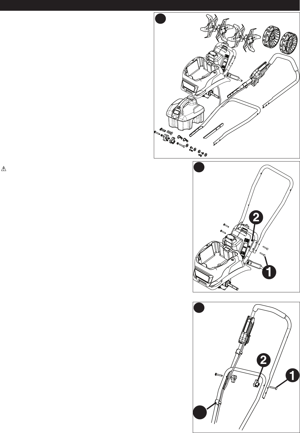
- ASSEMBLY INSTRUCTIONS 6
- OPERATING INSTRUCTIONS 8
- TROUBLESHOOTING GUIDE 10
- MODE D?EMPLOI 12
- TABLE DES MATIÈRES 13
- DANGER : 14
- DESCRIPTION FONCTIONNELLE 17
- DIRECTIVES DE MONTAGE 18
- NOTICE DʼUTILISATION 20
- GUIDE DE DÉPANNAGE 22
- MANUAL DE INSTRUCCIONES 24
- DESCRIPCIÓN DE LAS FUNCIONES 29
- INSTRUCCIONES DE ENSAMBLAJE 30
- INSTRUCCIONES DE OPERACIÓN 32
© 2020, manymanuals.fr. Tous droits réservés | 1.391 s |
 Manymanuals.com
 Manymanuals.de
 Manymanuals.fr
 Manymanuals.it
 Manymanuals.pl
 Manymanuals.cz
 Manymanuals.es
 Manymanuals-pt.com
Commentaires sur ces manuels